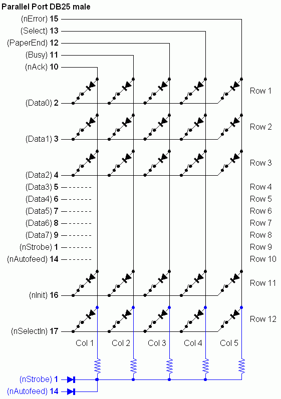
LPT-switch

Notes
- You can build as many rows as you need/want.
- Since DirectInput can only handle 32 buttons per device, PPJoy handles this interface as
two joysticks. Joystick one represents rows 1 to 6 (30 buttons) and Joystick 2 rows 7-12
(30 buttons).
- The pull-up arrangement, shown in Blue, should not be neccessary. It is included here
because the original diagram had them in.
- The pull-up resistors are 10k Ohm; the diodes are 1N4148.
- This diagram is very similar to, but not exactly the same as the original. This diagram
should be backward-compatible. If you use the original diagram buttons 55-60 (row 12)
will always be pressed.
- By default this interface reports 2 dummy axes to look more like a joystick. If you want
real axes it is possible to remap some of the buttons as axes.
- General notes about interface construction.
- This interface supports configurable timing parameters - see
Changing timing parameters on how to
change these values and
LPT-switch controller timing parameters for their meanings.
Credits
The original diagram and information for this interface can be found at
http://users.skynet.be/plipke/PF50HC/LPTswitch/index2.html.

