FMS Serial Interface v1.01
Introduction
Hardware
Protocol description
History
Credits
Introduction
As far as you know, when FMS migrated to Windows, it had some problems with
sencing transmiter signal. It's not evident, how to measure TX signal accurely
under Windows operating system. There can be several solution for that problem.
One solution is to use GamePort controller, to attach transmitter to computer.
But that's not the best way, because only 4 proportional chanels are allowed.
Futhermore, Gameport interface cable has relatively complicated construction.
Another solution is to write a good driver for FMS. But that's very difficult,
and require different drivers for each Windows type. We even can't guarantee,
that once been written, drivers will work in the future, when Microsoft will
reinvent it's Windows weel next time.
So, the third solution was selected, as the most acceptable. We've developped
interface cable with open protocol, to maintain all time-critical tasks. This
cable has the following advantages:
- It converts PPM signal from transmitter into serial data, and send that
data to computer via COM-port.
- No kernel-mode drivers required to process data. COM-port programming
is very easy under any kind of operating system.
- Cable contains microcontroller, but it has minimum of details, and requires
no tuning.
- Cable materials are cheap. All details cost less than 5$.
Archive files:
| /readme_en.htm |
this file |
| /readme_ru.htm |
russian description |
| /images/*.* |
schematics and other pictures, used in readme |
| /firmware/ |
original firmware files |
| /firmware/12C508.hex |
binary for PIC12C508 |
| /firmware/16C84.hex |
binary for PIC16C84(PIC16F84) |
| /firmware/sources/*.* |
firmware sources |
| /firmware.new/ |
new firmware by Rasmus Geidnert |
| /firmware.new/16C84.hex |
binary for PIC16F84(PIC16F84) |
| /firmware.new/sources/*.* |
new firmware sources
(with MPLAB project and stimulus files) |
Hardware
FMS cable contains Microchip PIC microcontroller,
that makes all work. There're 2 modifications of the cable, with PIC16F84
(PIC16C84) and with PIC12C508 microcontroller. I'd recomment to use PIC12C508,
because it is more cheap, and it doesn't requires crystal. But if you are
more familiar with PIC16F84 - no problems. You can chose any modification.
Those work both well.
You can see here all available schematics, for both PIC16F84/PIC12C508 and
all types of COM-ports (with 25-pin and 9-pin connectors).

Cable with PIC12C508, 9-pin connector (recommended).

Cable with PIC12C508, 25-pin connector.

Cable with PIC16F84 (PIC16C84), 9-pin connector.

Cable with PIC16F84 (PIC16C84), 25-pin connector.
Select any schematic, that is most suitable for you. The type of details
is not critical. You can use any PNP and NPN transistors (Q1 & Q2) with
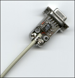
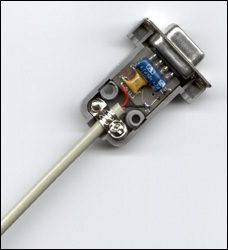
beta >100. I've prefered to use surface-mounted conponents, and here you
can see picture of cable (from first schematics) in assembled state and without
case. Device is very small and it was fited into 9-pin connector hood.


After you selected cable type and got all details, you need to programm PIC.
Select an appropriate firmware and burn it into your PIC chip. That's really
easy. Even if you don't have a PIC programmer, you can build your own one.
Schematic and software for home-built programmer are provided here: http://www.jdm.homepage.dk/newpic.htm.
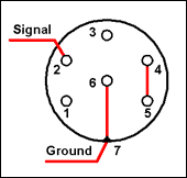
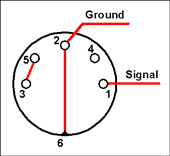
(!) Note, that cable schematics above have Hitec connector pinout
at another end. If you have another type of transmitter, you should connect
it to C1 (signal) and ground in different way. Here are wiring for some types
of transmitters that I know:
 |
- Hitec (all types)
- Futaba 8
- Futaba 9Z
|
 |
- Futaba SkySport
- Futaba AM
- Futaba 6
|
Protocol description
FMS cable uses the serial interface, to transmit data from TX to computer.
For proper work, COM-port must be configured in following way:
- 19200 baud
- 81N (8-bit data, 1 stop bit, no parity)
- RTS set to HI (+10v)
- DTR set to LO (-10v)
TX channel data been combined into packets and transmitted to computer. Data
is combined into packets for each PPM cycle:
- Every packet starts with 0xFF
- For each channel, 1 byte been added to packet (after 0xFF).
Channel byte value vary from 0 to 0xFE. Table below describe dependency between
pulse length and channel data.
| pulse length |
converted to
|
| 760 uS |
0x00
|
| 1528 us |
0x80
|
| 2284 us |
0xFE
|
each 1 in data is equal to 6 uS (+/- 6 uS in signal => +/- 1 in data).
EXAMPLE:
pause 0xFF 0x80 0x80 0x80 0x80 pause 0xFF 0x80 0x80 0x80 0x80 ...
That means, we have 4-channel transmitter, and all sticks are now in the
midle position.
(!) Note, when transmitter is off, cable sends to computer 0xFF bytes
constantly. That helps to determine, that cable itself is ok.
History
25.11.2000, version 1.00
First version of interface. PIC16F84(PIC16C84) and PIC12C508 are supported.
Firmware sources have comments in russian (I'm sorry, guys :) ).
28.02.2001, version 1.01
Added alternate firmware, written by Rasmus Geidnert.
New firmware transfers data after each PPM pulse, instead of PPM pause. That's
for sure, no collisions will happen if you use 8-channel TX. I don't know,
if an old firmware has ever had such problem, but anyway, Rasmus's idea is
nice, and his firmware should be more reliable. Firmware sources are now commented
in english.
Credits
This interface was designed specially for FMS team, that provide the best
free flying models simulator. Information about FMS serial interface cable
is freeware. You can freely use it for non-commercial purpuses and distribute
it to anyone, provided that all files are intact. You must distribute FMS
serial cable documentation only in original package. Commercial usage of this
information without author's permission is prohibited.
WWW:
http://www.rcdesign.ru - FMS serial interface
homepage. Original archive placed there.
http://simulator.home.pages.de
- FMS homepage.
Email:
Vitaly Puzrin - author of FMS serial
interface.
Rasmus Geidnert - author of the
alternate firmware for FMS serial cable.
Copyright © Vitaly Puzrin, RC Design
2000


